PCB winding assembly
Start with layer stack, conductor geometry, via current paths, insulation and the heat-transfer interface.
PRINTED WINDINGS / WHEEL-END DUTY
Choose a winding architecture and a drive duty for the same shallow installation. Explore PCB-stator assemblies or a low-profile wheel module without treating the two as interchangeable specifications.
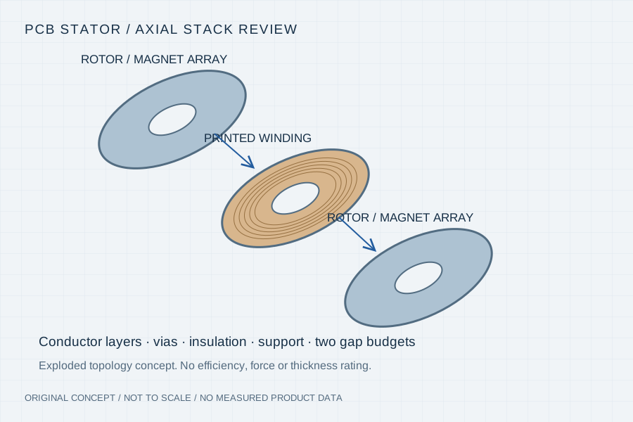
PCB describes how the active conductors are made. Wheel drive describes what the assembly must do. A fan, pump or compact actuator may start from a PCB winding study; an AGV wheel begins with mass, traction, slope, acceleration and stopping duty. Some projects can combine the two, but geometry, losses and the load path must justify that choice.
Start with layer stack, conductor geometry, via current paths, insulation and the heat-transfer interface.
Start with wheel radius, supported load, tractive effort, speed, duty cycle and the required brake or gearbox.
Provide the complete voltage range, current limits and regenerative-energy handling, not just the nominal 48V label.
A project can require either path or both. Each path needs its own acceptance evidence; neither a PCB construction nor a nominal voltage establishes a qualified wheel-drive rating.
| Review path | Inputs that make it actionable | Evidence to agree |
|---|---|---|
| PCB stator / rotor set | OD, bore, active thickness, layer/conductor constraints, current and cooling | Winding resistance, insulation, phase balance and thermal validation at the required duty |
| 48V wheel / side-mount module | Battery min/max voltage, wheel radius, load, slope, acceleration and speed | Starting and repeated-load tests, winding/drive temperatures and supply limits |
| Direct drive versus gearing | Wheel torque-speed cycle, permissible reduction, backlash and package | Motor operating points, mechanical efficiency assumptions and output-load path |
| Brake and regeneration | Holding requirement, stopping cycle, power-loss behaviour and battery limits | Separate holding-brake verification from stopping and regenerative-energy validation |
| AUV / wet or clean environments | Pressure, media, seals, corrosion and acoustic conditions | Project-specific sealing/material/acoustic test plan, not an application label |
Read the installed section
A PCB-stator concept forms winding conductors in patterned copper layers. In an ironless axial-flux arrangement, the board sits in the working magnetic gap between rotor structures. Layer interconnects, lead exits, support features and insulation remain part of the electrical and mechanical design.
Copper thickness and routing affect resistance, current distribution, manufacturability and thermal behaviour. Board thickness, rotor retention and clearance affect the magnetic gap. Review the complete stack and cooling route before assigning torque or efficiency targets.
Technical context: ECM — PrintStator design-to-manufacture ↗
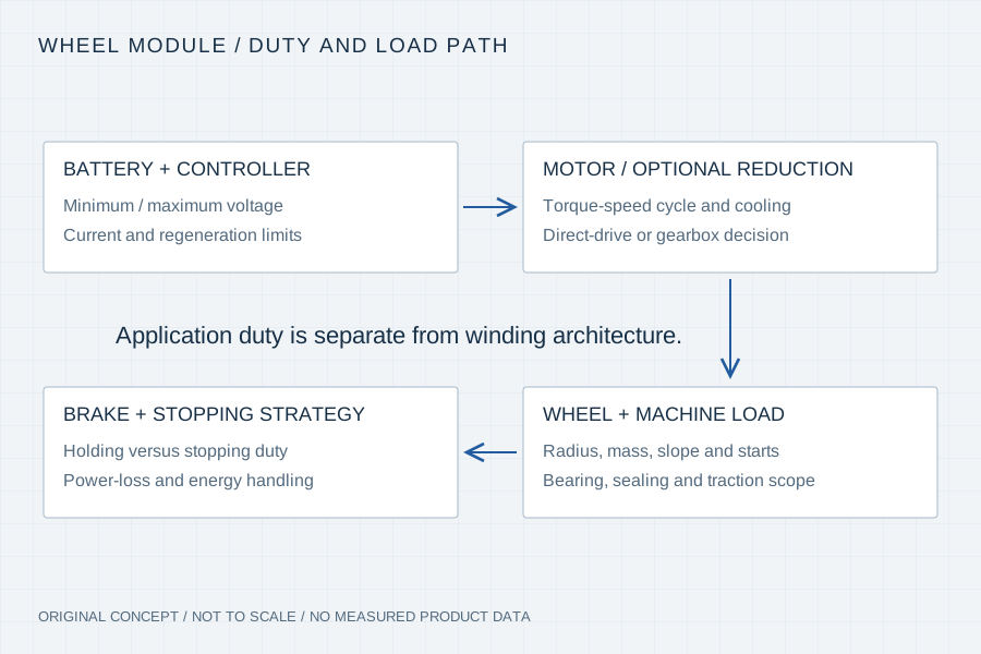
If the project supplies a board layout, identify the stack-up, fabrication files, copper and via requirements and electrical test specification. If the winding is to be developed, begin with the torque-speed, voltage and envelope brief. Tool/software licensing and design ownership are agreed separately; no access to a third-party proprietary design platform is implied.
Give the mass distribution, driven-wheel count, tyre radius, floor/slope condition, acceleration and time spent at each speed. Include loaded starts, reversals and sustained grades. These inputs help establish wheel torque-speed requirements; the motor point then depends on direct drive or the chosen reduction.
Repeated low-speed starts may be dominated by copper heating, while higher-speed operation brings additional electrical and mechanical losses. Include controller efficiency, regeneration limits and actual cooling. A single efficiency number or a generic ambient derating percentage cannot qualify the complete module.
01 / Review gate
Agree layer/connection traceability, continuity, resistance and insulation test conditions with the fabrication and winding drawings.
02 / Review gate
Define gap control, axial attraction/load path, retention, runout and bearing responsibility with the installed section.
03 / Review gate
Record voltage, current, torque/speed, temperature and operating time for the representative load cycle, then compare with agreed limits.
Your inputs / an actionable review
Enter known constraints or “Need advice”. Mark documents you can provide; this records availability, not file inspection or engineering approval. No document is required to start a discussion.
4 document topics to discuss. Selected documents have not been uploaded or reviewed.
Carry This Brief into the Web Inquiry ↗Your email, already structured
Use the same brief in your email client or copy it with our address. Add photos or drawings as email attachments when available.
Downloads contain your entered details and file links, including contact details when provided. Keep or share them according to your project’s confidentiality requirements. Saving a draft does not send it to us. The JSON restores the inquiry form; it is not a CAD attachment.
Your inputs remain in this page until you send the web form. If your email app omits a long message, copy the complete brief above.
No. The wheel application must separately satisfy torque-speed, thermal, bearing, braking, sealing and controller requirements.
No. Specify battery minimum/maximum voltage, current limits, undervoltage behaviour and regeneration handling. The nominal supply label is only a starting point.
Only after a proposed configuration and comparison method are defined and supported by evidence. No third-party percentage is transferred to our project ratings.
Send OD, bore, installed depth, torque-speed duty, voltage/current and cooling constraints. A development review can start from those requirements; a finished winding design is not mandatory.
Manufacturer example of PCB winding design inputs and fabrication output. ECM software and product claims remain its own.