Clear bore after integration
Budget for winding support, rotor carrier, retention and moving cable clearances, not just the nominal magnetic opening.
IRONLESS WINDING / SEGMENTED MAGNETIC ROTOR
Bring a shallow axis, a large clear bore and smooth low-speed motion into one integration review. Define the ironless winding, Halbach rotor and drive together before freezing the mechanical package.
Precision scanning, optical pointing and force-feedback joints expose disturbances that a headline torque rating cannot describe. Start with the speed, load, motion error and measurement bandwidth that your machine actually needs. A slotless winding can remove tooth-related cogging; bearings, drive current, feedback and assembly errors still belong in the motion budget.
Budget for winding support, rotor carrier, retention and moving cable clearances, not just the nominal magnetic opening.
Separate continuous torque and cooling from short peak-current events. Include the temperature rise and repetition rate.
Review current ripple, switching strategy and feedback with the selected amplifier before comparing motor-only motion claims.
Read the installed section
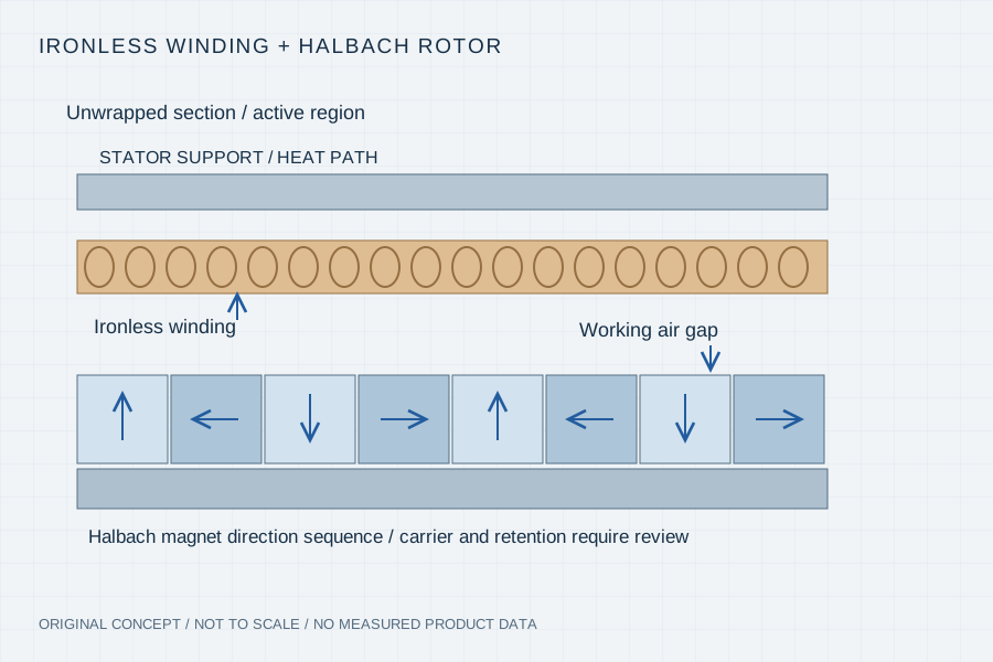
Ironless construction removes the stator teeth responsible for slot-related cogging. A Halbach array uses changing magnetisation directions to shape the field toward the working region. These choices can work together, but the array alone does not specify cogging, back-EMF quality or the complete motor topology.
Review the winding support, usable magnetic gap, magnet direction sequence and rotor carrier in the same section drawing. Our review can start from a rotor-only, stator-only or matched kit scope; the proposed build route is confirmed against the drawing.
Technical context: ThinGap — slotless technology ↗
These are inputs for a project review, not published performance ratings. A numerical target becomes meaningful when its operating and measurement conditions are agreed.
| Decision | Specify in the brief | Verify on the proposed build |
|---|---|---|
| Cogging / torque ripple | Unpowered drag versus powered ripple; speed, load and bandwidth | Distinguish no-current cogging tests from driven-axis ripple measurements |
| Back-EMF quality | Speed, waveform sampling, phase balance and THD calculation method | Record phase waveforms and test conditions, rather than assuming a universal THD value |
| Winding and drive | Voltage range, phase-current limits, switching frequency and feedback | Review current-loop behaviour and winding temperature under the required cycle |
| Rotor retention | Maximum speed, overspeed requirement, adhesive, sleeve and available gap | Agree retention evidence and balance/runout acceptance before assembly |
| Thermal path | Stator support, housing contact, cooling and temperature limits | Measure winding/assembly temperatures in the agreed installation |
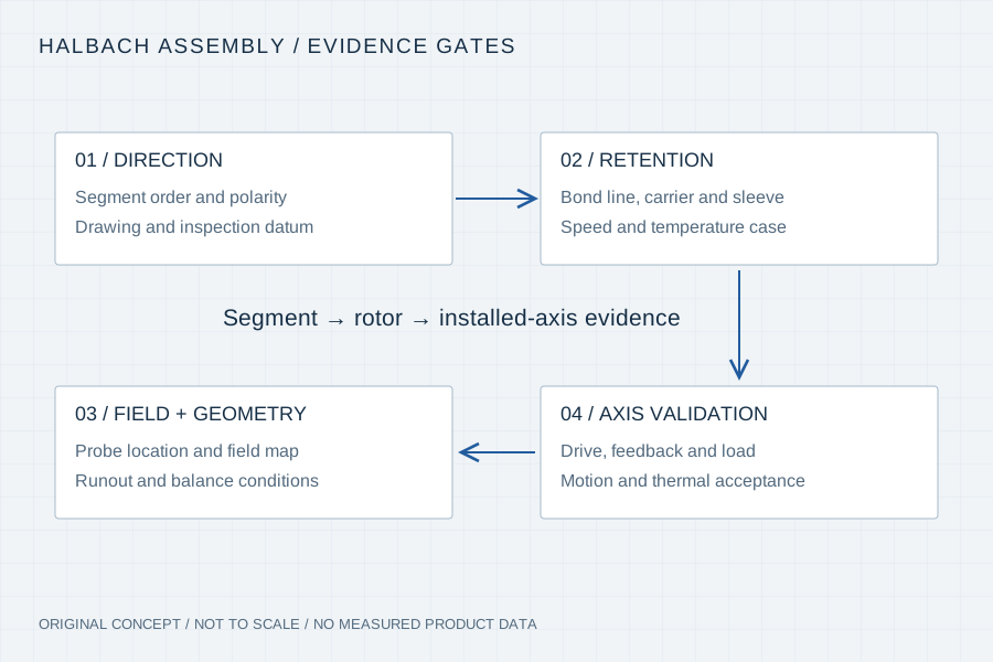
Segment orientation, polarity, adhesive gap and fixture datums affect the final field and air-gap geometry. Discuss pre-magnetised segment assembly versus post-assembly magnetisation with the supplier. A post-assembly route is feasible only when the geometry and magnetising equipment support the required direction pattern.
A composite sleeve or other retention feature must be reviewed for speed, thermal expansion, bond line, rotor growth and inspection access. A sleeve material name is not an overspeed qualification. Freeze the installed radial and axial section with the retention method included.
For an optical scan, specify speed uniformity under the intended load. For a haptic joint, specify backdrive and torque response with the controller active. Semiconductor equipment may add cleanliness, vacuum or outgassing requirements; those require explicit material and process review.
01 / Review gate
Agree how polarity, segment order and field uniformity are checked, including the probe position and drawing revision.
02 / Review gate
Define rotor runout, bonding/retention acceptance and balance conditions with the actual carrier and sleeve installed.
03 / Review gate
Keep phase resistance, back-EMF, winding temperature and loaded motion results traceable to the sample and test setup.
Your inputs / an actionable review
Enter known constraints or “Need advice”. Mark documents you can provide; this records availability, not file inspection or engineering approval. No document is required to start a discussion.
4 document topics to discuss. Selected documents have not been uploaded or reviewed.
Carry This Brief into the Web Inquiry ↗Your email, already structured
Use the same brief in your email client or copy it with our address. Add photos or drawings as email attachments when available.
Downloads contain your entered details and file links, including contact details when provided. Keep or share them according to your project’s confidentiality requirements. Saving a draft does not send it to us. The JSON restores the inquiry form; it is not a CAD attachment.
Your inputs remain in this page until you send the web form. If your email app omits a long message, copy the complete brief above.
No. Slotless describes the active stator construction; Halbach describes a magnetisation arrangement. Confirm both in the proposed section drawing.
It removes the tooth-related cogging mechanism. Current ripple, bearing drag, imbalance, feedback errors and structural resonances still need system-level validation.
Yes. Specify the carrier, magnet geometry, polarity sequence, retention, temperature, speed and inspection boundary. A rotor-only proposal does not qualify the customer’s complete motor.
A requested date can be included in the brief. The schedule follows drawing, material, tooling and supplier-capacity review and is confirmed in the quotation.
Manufacturer context for tooth-related cogging and the importance of the motor/drive combination; its product metrics are not our ratings.
Manufacturer example of an ironless stator, Halbach rotor and drive/integration considerations; no equivalence or affiliation is implied.