Scan / index profile
Provide speed, acceleration, dwell, reversal and settling conditions, including the load and axis orientation.
SEMICONDUCTOR AXIS / SCAN AND SETTLING CONDITIONS
Turn a smooth-motion requirement into a measurable axis brief. Review motor depth, bearing and feedback architecture, service routing and the scan or settling conditions that matter to the process.
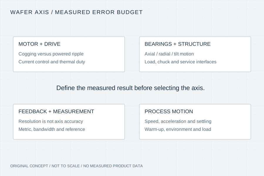
A slotless motor addresses a particular magnetic disturbance. The process still experiences current-loop effects, bearing motion, encoder error, structure, payload and thermal drift. Define whether the concern is velocity uniformity, position error, settling, repeatability or another measured quantity before comparing motor architectures.
Provide speed, acceleration, dwell, reversal and settling conditions, including the load and axis orientation.
State the metric, units, sampling/filter bandwidth and reference instrument; encoder resolution alone is insufficient.
Identify clean-air or vacuum conditions, cable/rotary-union services and the thermal path to the machine.
These are distinct quantities. Provide the actual process requirement and measurement setup instead of treating one catalogue number as a substitute for all of them.
| Motion decision | Specify with the load case | Evidence to agree |
|---|---|---|
| Velocity uniformity | Scan speed, payload, direction, bandwidth and time window | Measured velocity deviation under the representative operating profile |
| Position / settling | Move distance, acceleration, allowed error band and settling interval | Response trace and the defined in-position criterion |
| Geometric motion | Chuck/load location, reference plane and axial/radial/tilt requirements | Measurement method, reference datum and assembled configuration |
| Thermal drift | Warm-up, duty, ambient and cooling/support conditions | Temperature and drift records with declared time and setup |
| Service and environment | Vacuum/clean requirements, chuck services and travel | Material/process requirements and service-routing acceptance |
Read the installed section
Slotless or ironless construction can remove the stator-tooth cogging mechanism. The installed motion result depends on the drive, feedback, bearings, load and structure working together. A low-profile motor can help packaging without establishing the geometric or servo performance of the completed stage.
The zero-cogging term in the route identifies the architecture search intent. It does not assert zero powered torque ripple, zero vibration or a numerical wafer-stage rating. Agree the applicable test method and conditions for the proposed assembly.
Technical context: Aerotech — WaferMaxT architecture and integration ↗
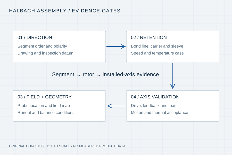
Resolution, encoder error, interpolation, mounting and control behaviour have different effects. State the reference measurement and how the axis result is evaluated. The motor/encoder proposal should identify the required signals and integration responsibility without substituting a nominal count for process performance.
Include chuck support, vacuum or pneumatic passages, rotary unions, cable exits and the payload centre of mass. A service component or bearing can set the installed height or load path even when the electromagnetic stack is thin.
Specify the environment, exposed materials, allowable processes and the qualification boundary. An application label does not establish cleanliness, vacuum suitability or outgassing performance. Review the requested conditions with the component supplier and the equipment owner.
01 / Review gate
Identify motor, drive, feedback, bearing, chuck/services and thermal interfaces in one installation drawing.
02 / Review gate
Freeze metric, units, load, bandwidth, warm-up and acceptance method before recording results.
03 / Review gate
Compare the representative scan or settling trace with the agreed requirement and retain the test configuration and open issues.
Your inputs / an actionable review
Enter known constraints or “Need advice”. Mark documents you can provide; this records availability, not file inspection or engineering approval. No document is required to start a discussion.
4 document topics to discuss. Selected documents have not been uploaded or reviewed.
Carry This Brief into the Web Inquiry ↗Your email, already structured
Use the same brief in your email client or copy it with our address. Add photos or drawings as email attachments when available.
Downloads contain your entered details and file links, including contact details when provided. Keep or share them according to your project’s confidentiality requirements. Saving a draft does not send it to us. The JSON restores the inquiry form; it is not a CAD attachment.
Your inputs remain in this page until you send the web form. If your email app omits a long message, copy the complete brief above.
No. It addresses tooth-related cogging; driven ripple and motion error also depend on current regulation, feedback, bearings and the installed structure.
No. Specify the required measured axis result, reference instrument, load and evaluation method. Resolution is only one part of the feedback system.
No. Supply the actual environment and material/process requirements so the proposal defines a qualification scope for the equipment.
Yes. Send the installed envelope, process motion profile, load and current error/acceptance definition. The review can identify what further architecture information is needed.
Primary example of low-profile wafer-stage integration, bearings, motion and service features. Its stage ratings are not our motor ratings.