Installed package
Send chassis and mounting datums, ground clearance, wheel envelope and cable/service access across the steering range.
48V MOBILE BASE / WHEEL LOAD AND INSTALLED HEIGHT
Start with chassis height and the wheel’s working cycle. Review a hub or side-mounted pancake drive with the bearing load path, optional gearing, holding brake, controller and battery limits included.
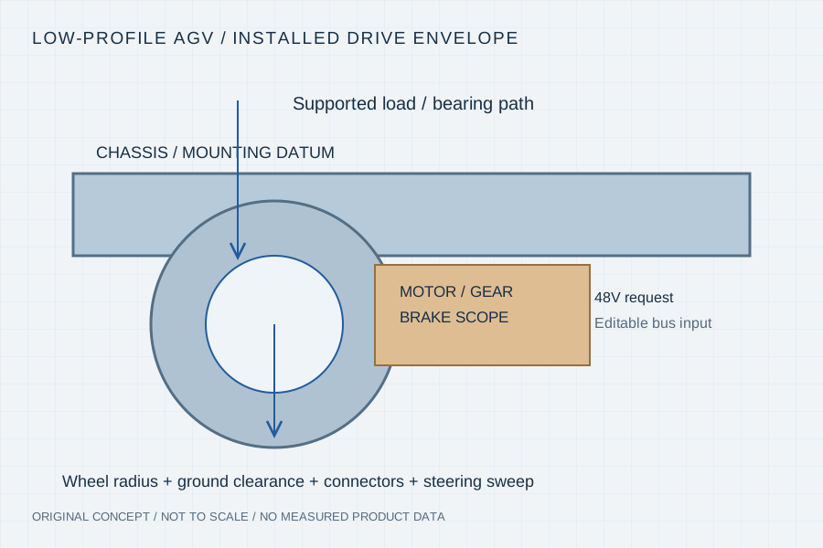
Wheel radius, ground clearance, bearing support, gearbox, brake, connector bends and mounting features all affect the installed package. The load cycle then determines the operating torque, speed, current and temperature. Review these together before choosing hub direct drive or a side-mounted reduction.
Send chassis and mounting datums, ground clearance, wheel envelope and cable/service access across the steering range.
Provide supported mass, driven-wheel count, slope, acceleration, speed, loaded starts and time at each condition.
State battery min/max voltage, current and regeneration limits, plus separate holding and stopping requirements.
Provide the machine conditions and identify which component supplies each function. No generic payload or ambient derating percentage is used as an approval.
| Integration decision | Inputs to provide | Acceptance scope to agree |
|---|---|---|
| Height and steering clearance | Chassis datums, tyre radius, mounting, steering sweep and service space | Complete installed envelope with brake, connectors and retained hardware |
| Wheel torque-speed duty | Mass distribution, driven wheels, slope, speed and acceleration | Load-cycle assumptions and motor/transmission operating points |
| Repeated starts / thermal | Start frequency, duration, dwell, cooling and temperature locations | Representative repeated-load temperature and current tests |
| Bearing / mechanical load | Radial, axial, overhung and shock load cases; support arrangement | Bearing and structure responsibility, geometry and mechanical verification |
| Holding / stopping / energy | Holding condition, stopping cycle, power-loss behaviour and regeneration limits | Separate brake, controller and vehicle acceptance requirements |
Read the installed section
A wheel module may place a motor at the hub or connect a shallow motor through a suitable reduction. The motor operating point depends on wheel torque-speed demand and transmission assumptions. Bearings and structural interfaces must carry the specified loads independently of a headline motor torque number.
The preset 48V value is an editable nominal bus request. Confirm the full battery range, drive limits and energy-handling strategy. No payload, slope, efficiency or ingress rating is inferred from this guide.
Technical context: maxon — logistics wheel-drive integration ↗
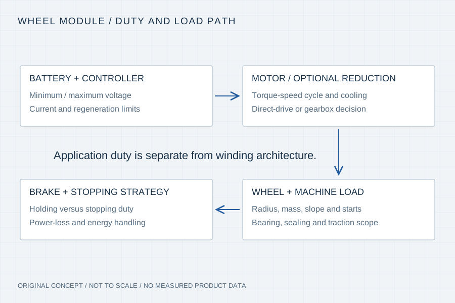
Wheel radius, reduction and losses connect motor torque to wheel effort, while mass distribution, floor conditions and vehicle geometry affect traction and support loads. Supply the assumptions rather than treating a motor rating as a complete vehicle capability.
Loaded starts, grades, turns, reversals and continuous travel can stress the drive differently. Specify duration and repetition, not just peak torque. Include the cooling path and relevant temperature limits so the proposed motor and drive can be reviewed against the actual cycle.
A holding brake does not by itself define the vehicle stopping strategy. Identify the required behaviour and which controller, battery and mechanical components participate. Agree these system-level requirements with the vehicle engineer before releasing a module design.
01 / Review gate
Freeze mounting datums, bearing responsibility, drive/gear/brake scope and installed service clearances.
02 / Review gate
Record load, wheel speed, supply range, current, starts and temperatures, with the controller/battery configuration identified.
03 / Review gate
Agree the representative tests for motion, holding/stopping, environment and serviceability with the machine owner.
Your inputs / an actionable review
Enter known constraints or “Need advice”. Mark documents you can provide; this records availability, not file inspection or engineering approval. No document is required to start a discussion.
4 document topics to discuss. Selected documents have not been uploaded or reviewed.
Carry This Brief into the Web Inquiry ↗Your email, already structured
Use the same brief in your email client or copy it with our address. Add photos or drawings as email attachments when available.
Downloads contain your entered details and file links, including contact details when provided. Keep or share them according to your project’s confidentiality requirements. Saving a draft does not send it to us. The JSON restores the inquiry form; it is not a CAD attachment.
Your inputs remain in this page until you send the web form. If your email app omits a long message, copy the complete brief above.
No. Supply the minimum/maximum battery voltage, current, regeneration limits and wheel-duty cycle. The nominal bus label is only a starting request.
No. Holding and stopping are different requirements. Define the vehicle behaviour and complete braking/control/energy-handling scope with the machine engineer.
No. Vehicle geometry, traction, load distribution, wheel size, reduction and thermal duty must be reviewed before a qualified proposal.
Yes. Send the same installed envelope and wheel-duty requirements for both. The review should identify changed components, operating points and acceptance conditions.
Primary manufacturer context for a modular motor, wheel, brake and control approach. Its payload and protection claims remain product-specific.