Gearbox interface
Provide the exact reducer model, ratio, register, fastening and rotor attachment drawing. A family number is not a verified interface match.
48V JOINT / MOTOR-GEAR-BEARING INTERFACE
Build the joint around the complete installed section. Review a 60–85 mm diameter packaging study with the motor, strain-wave gear, bearings, brake and feedback visible together. The diameter range is a design brief, not a list of available frames.
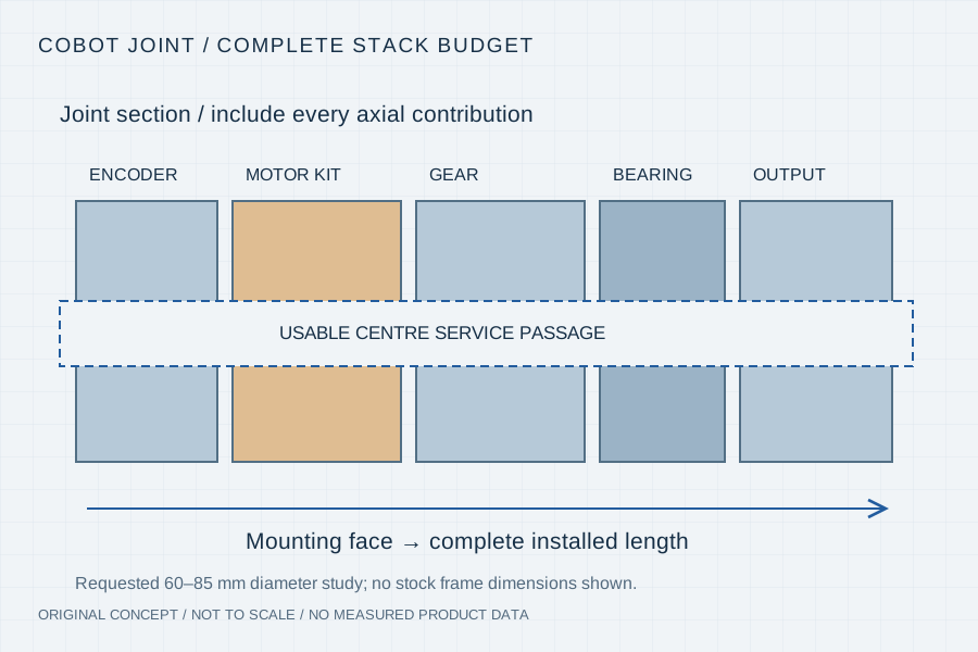
A rotor retainer, encoder, brake, winding end and cable bend can consume the axial space saved by a short stator. Start from the joint’s external mounting faces and service access. Treat the motor’s active length, its supplied assembly length and the complete installed joint length as different dimensions.
Provide the exact reducer model, ratio, register, fastening and rotor attachment drawing. A family number is not a verified interface match.
Separate motor-side continuous and peak torque from output torque, with speed, dwell, cooling and temperature limits.
Identify the bearing arrangement, output loads, encoder location and brake scope rather than assigning them implicitly to the motor kit.
Read the installed section
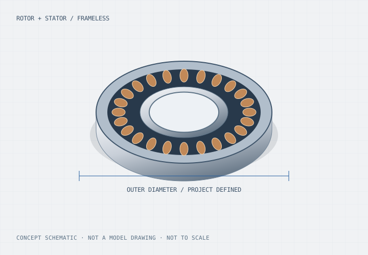
A frameless kit supplies the electromagnetic rotor and stator for integration into the joint structure. The housing, bearings and gear interface determine how the air gap is held and how load and heat move through the assembly. A nominal motor diameter does not establish the complete joint envelope.
The 48V value is an editable nominal bus request. Include supply minimum/maximum, controller current limits and the motor-side operating cycle. Review the final geometry and electrical combination before treating any proposed winding as a fit.
Technical context: Kollmorgen — frameless motor integration ↗
Use the actual reducer drawing and machine duty to define a project-specific proposal. These inputs do not establish a qualified motor frame or a guaranteed gear-family match.
| Interface decision | Send with the drawing | Acceptance evidence to agree |
|---|---|---|
| Installed depth | Mounting faces, stator length, winding ends, brake/encoder and assembly clearance | Section drawing with each supplied and retained part identified |
| Reducer and rotor mounting | Exact gearbox reference, ratio, bolt pattern, register and rotor support | Fit, runout and air-gap control against the agreed datums |
| Motor-side duty | Output load cycle, reduction assumptions, motor speed and cooling | Current/torque-speed and temperature records for the representative cycle |
| Service passage | Connector envelope, usable bore, bend radius and joint travel | Installed routing assessment across the motion range |
| Feedback and holding | Encoder interface/location and brake holding/power-loss requirements | Feedback integration and separate brake/axis acceptance plan |
Gear efficiency, acceleration, inertia, friction and time at load affect the motor operating point. Provide the reduction and cycle assumptions, then agree which loads and losses are included in the assessment. A motor-only peak rating cannot establish an output joint’s continuous capability.
The winding sensor, motor housing, nearby gearbox and accessible joint surface can have different limits and thermal histories. Specify where each temperature is measured and the cooling/support conditions. No universal surface limit or fixed torque derating is applied by this guide.
List the stator/rotor kit, magnets and retention, bearings, gear, feedback, brake and harness responsibilities. Keep inspection datums and assembly operations aligned with that scope. The prototype should answer a defined fit, thermal or motion question before production release.
01 / Review gate
Resolve gear register, rotor retention, winding support, air gap and full installed depth using one revision-controlled section.
02 / Review gate
Record bus voltage, current, speed, load, cooling and sensor locations during the representative joint cycle.
03 / Review gate
Agree the output-load, feedback, routing and holding tests with the complete configuration identified.
Your inputs / an actionable review
Enter known constraints or “Need advice”. Mark documents you can provide; this records availability, not file inspection or engineering approval. No document is required to start a discussion.
4 document topics to discuss. Selected documents have not been uploaded or reviewed.
Carry This Brief into the Web Inquiry ↗Your email, already structured
Use the same brief in your email client or copy it with our address. Add photos or drawings as email attachments when available.
Downloads contain your entered details and file links, including contact details when provided. Keep or share them according to your project’s confidentiality requirements. Saving a draft does not send it to us. The JSON restores the inquiry form; it is not a CAD attachment.
Your inputs remain in this page until you send the web form. If your email app omits a long message, copy the complete brief above.
No. The URL identifies a requested packaging study in that diameter range. Actual model dimensions and ratings require an approved drawing and operating conditions.
No. Use the complete reducer model and interface drawing, including the register, fasteners, attachment and bearing arrangement.
No. It is the starting nominal bus request and can be edited. Minimum/maximum voltage, controller limits and the selected winding still require review.
Yes. Provide the outer envelope, retained interfaces and current load assumptions, and mark missing documents as topics to discuss.
Primary context for the housing, shaft, bearings, sensing and other components around a frameless kit. Its product details are not our ratings.