Clear bore
Size the usable opening for connectors and motion, not just the nominal shaft ID.
HOLLOW SHAFT / THROUGH BORE
Route services through the axis while keeping axial height under control. Define the clear passage, shaft support and cable path as one mechanical envelope.
Send Us Your Space Constraints ↗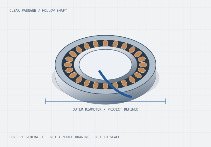
Before selecting a winding
Size the usable opening for connectors and motion, not just the nominal shaft ID.
Check radial lead clearance and strain relief against the surrounding enclosure.
Separate motor torque from permitted axial, radial and moment loads.
A hollow shaft is useful only if cables, tubing and connectors can pass through the installed mechanism. Include rotary travel, bend radius, protective sleeves and service access. For continuously rotating equipment, a slip ring or rotary union is a separate design decision.
A short motor body can still need a longer assembly to support an overhung load. Specify the shaft extension, load application point, bearing arrangement and runout target. Review flange faces and fastening access so the thin motor can actually be assembled and maintained.
Encoder location, connector orientation and electrical noise can constrain a through-bore arrangement. Identify the controller, feedback interface and shielding strategy early. Prototype inspection should include bore clearance, shaft runout, loaded temperature and motion repeatability in the receiving machine.
Confirm the finished drawing. Sleeves, retaining parts, seals and feedback hardware can reduce the usable passage.
That depends on the selected bearing arrangement and load case. Motor torque alone does not establish structural load capacity.